
Exploring the World of Diospyros kaki: A Deep Dive
The Enigmatic Kaki Fruit
The Kaki fruit, also known as the Japanese persimmon or Diospyros kaki, is indeed a fascinating and enigmatic fruit with a rich history and unique characteristics.
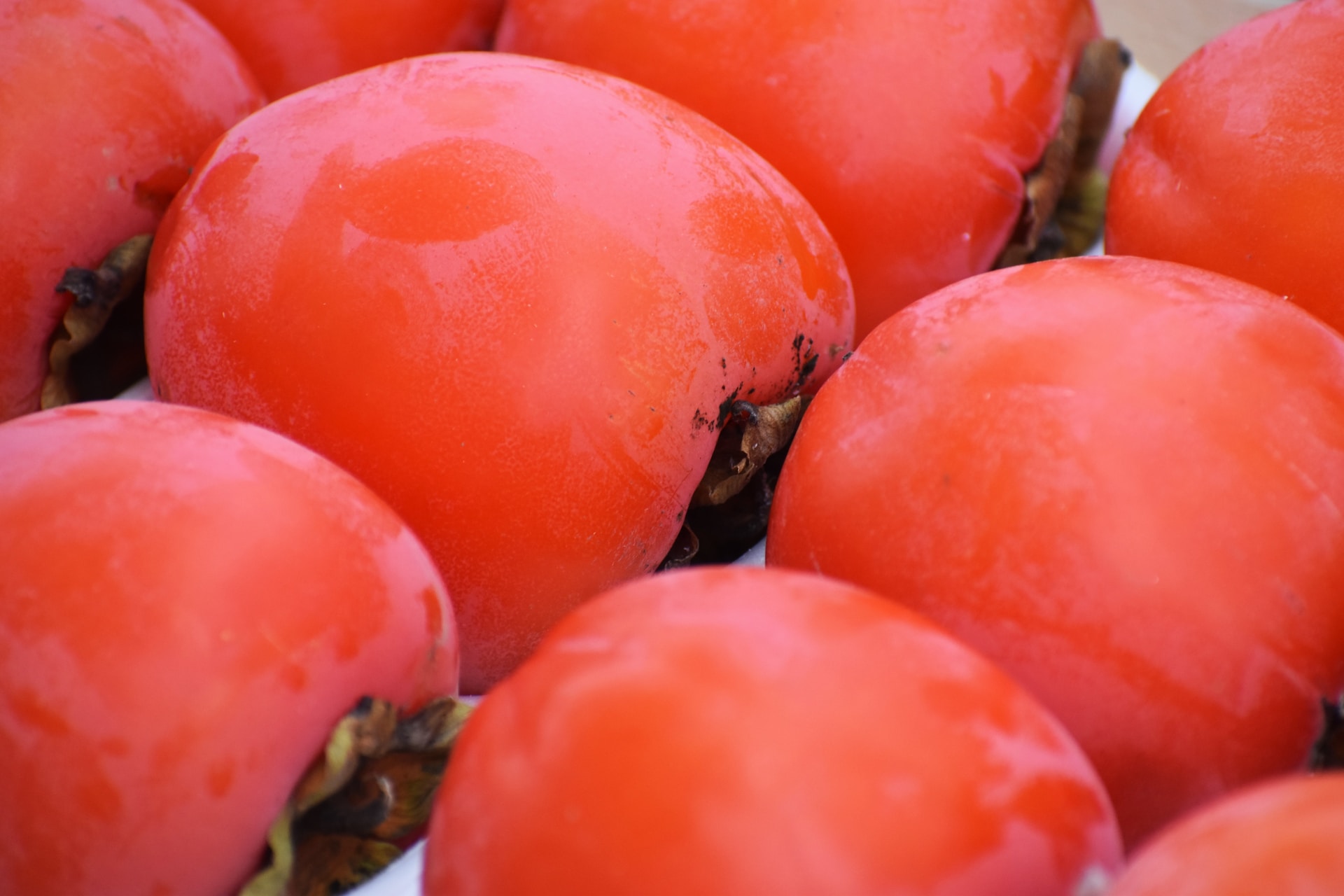
Appearance and Varieties: Kaki fruits come in various shapes, sizes, and colors depending on the variety and ripeness. They can be spherical or slightly flattened, and their skin ranges from pale yellow to deep orange-red. Some varieties even have a waxy bloom on the skin, giving them a frosted appearance.
Flavor and Texture: One of the most intriguing aspects of Kaki fruit is its transformation during ripening. When unripe, the fruit is incredibly astringent due to high levels of tannins. Eating an unripe Kaki can leave your mouth dry and puckered. However, as it ripens, the fruit undergoes a remarkable change in taste and texture. The flesh becomes sweet, smooth, and custard-like, making it a delightful and flavorful treat.
Cultural Significance: Kaki fruit has a long history of cultivation in East Asia, particularly in Japan, China, and Korea. It holds cultural significance and is often associated with autumn. In Japan, Kaki fruit is a symbol of good luck and prosperity. They are used in various traditional dishes, desserts, and even as decorations during the fall season.
Health Benefits: Kaki fruit is not only delicious but also nutritious. It is a good source of vitamins A and C, as well as dietary fiber. These nutrients contribute to its reputation as a healthy snack and a natural way to satisfy your sweet tooth.
Culinary Uses: Kaki fruit can be enjoyed in numerous ways. When fully ripe, you can eat it fresh, either by cutting it into slices or scooping out the soft flesh with a spoon. Some people like to peel the skin, while others prefer to eat it with the skin intact. Kaki can also be used in salads, smoothies, jams, and baked goods. Dried Kaki, known as “hoshigaki” in Japan, is a popular treat and involves air-drying the fruit, which intensifies its sweetness.
The Botanical Marvel
Taxonomy and Origin
Taxonomy:
The Kaki fruit, scientifically known as Diospyros kaki, belongs to the kingdom Plantae, phylum Angiosperms, class Eudicots, order Ericales, and family Ebenaceae. This family encompasses a diverse group of flowering plants, and the Diospyros genus includes a wide range of species, including the Kaki fruit.
Within the species Diospyros kaki, there are several cultivated varieties, each with its own unique characteristics in terms of fruit size, shape, color, and flavor. Some popular Kaki varieties include Fuyu, Jiro, and Hachiya, among others.
Origin:
The exact origin of the Kaki fruit can be traced back to China, where it has been cultivated for over a thousand years. It is believed that the cultivation of Kaki began in the Shanxi province of China. From there, the fruit spread to Japan, Korea, and other parts of Asia.
Kaki fruit has a rich history in East Asian cultures. In Japan, it has been cultivated for centuries and is considered a symbol of autumn. The Japanese even have a tradition of drying Kaki fruit to make “hoshigaki,” a sweet and chewy delicacy. In Korea and China, it is also a popular fruit, used in various culinary applications and enjoyed for its unique flavor and nutritional benefits.
Over time, Kaki fruit made its way to other parts of the world, including the Mediterranean region, the United States, and South America. Today, it is grown in many countries with suitable climates, and its popularity as a sweet and nutritious fruit continues to grow globally.
Botanical Features
The Kaki fruit, also known as the Japanese persimmon, exhibits several distinctive botanical features:
- Tree: The Kaki fruit tree is a deciduous tree that can grow to varying heights, typically ranging from 6 to 25 feet (2 to 8 meters) tall, depending on the variety and growing conditions. It has a spreading canopy with glossy, dark green leaves.
- Leaves: The leaves of the Kaki tree are elliptical or ovate and can be up to 6 inches (15 centimeters) long. They are arranged alternately on the branches and have a vibrant green color.
- Flowers: Kaki trees produce small, inconspicuous flowers. These flowers are typically pale yellow to creamy-white in color and are either solitary or clustered. They are not particularly showy and are often overlooked compared to the fruit.
- Fruit: The most distinctive feature of the Kaki tree is its fruit. Kaki fruit is typically spherical or slightly flattened, resembling a tomato in shape. The fruit’s skin varies in color from pale yellow to deep orange-red, and some varieties may have a waxy bloom, giving them a frosted appearance.
- Fruit Size: Kaki fruit sizes can also vary depending on the variety, but they are usually about the size of a small to medium apple or tomato, typically ranging from 1.5 to 4 inches (4 to 10 centimeters) in diameter.
- Flesh: The inner flesh of the Kaki fruit is the most intriguing aspect. When unripe, it is extremely astringent due to high tannin content, making it inedible and causing a dry, puckering sensation in the mouth. However, as the fruit ripens, the flesh becomes sweet, smooth, and custard-like, with a delectable flavor and texture.
- Seeds: Kaki fruits typically contain several small, flat, and dark brown seeds. These seeds are not commonly consumed, as the focus is primarily on the sweet and flavorful flesh.
- Maturation: Kaki fruit undergoes a unique ripening process, transitioning from astringent and unpalatable when unripe to sweet and enjoyable when fully ripe. The transformation involves a reduction in tannin levels and a softening of the flesh.
- Harvest: Kaki fruit is typically harvested in the late autumn months when it reaches its peak ripeness. The exact timing of the harvest may vary depending on the variety and local climate.
Varieties of Diospyros kaki
Diospyros kaki, commonly known as the Kaki fruit or Japanese persimmon, boasts a wide range of cultivated varieties, each offering its own unique set of characteristics in terms of fruit size, shape, color, flavor, and ripening behavior. Among the most well-known Kaki varieties are Fuyu, Jiro, and Hachiya, which exemplify the diversity within this species.
Fuyu is perhaps one of the most popular Kaki varieties globally. It is recognized for its squat, tomato-like shape and vibrant orange skin. Fuyu Kaki is unique in that it can be consumed both when still firm and crisp, resembling the texture of an apple, or when fully ripe, at which point it becomes sweet, succulent, and non-astringent. This versatility makes Fuyu Kaki a favored choice for fresh consumption, salads, and various culinary applications.
Jiro Kaki is another notable variety, often characterized by its round and flat shape. It tends to be smaller than some other varieties and exhibits a less pronounced astringency even when unripe. Jiro Kaki is preferred by many for its mild, sweet flavor and can be enjoyed when still firm or fully ripened, making it an excellent snacking choice.
In contrast, Hachiya Kaki, with its acorn-like shape, is known for its extreme astringency when unripe. To enjoy Hachiya Kaki at its best, it must be fully ripened until the flesh becomes soft and custard-like. At this stage, it offers a remarkably sweet and rich flavor. Hachiya Kaki is often used in baking and dessert recipes due to its luscious texture and intense sweetness.
Beyond these three popular varieties, there are numerous other Kaki cultivars, each with its own distinct characteristics, including variations in skin color, size, and flavor profiles. Some Kaki varieties are specifically bred for their unique attributes, catering to different tastes and culinary uses.
Fun Facts about Kaki Fruit
- Transformational Ripening: One of the most fascinating aspects of Kaki fruit is its ripening process. When unripe, it is extremely astringent due to high levels of tannins, making it unpleasant to eat. However, as it ripens, it undergoes a remarkable transformation, turning sweet, smooth, and custard-like, making it a delightful and flavorful treat.
- Autumn Symbolism: In Japan, the Kaki fruit is strongly associated with autumn and is often referred to as the “fruit of autumn.” It is a symbol of good luck and prosperity during this season and is used in various traditional dishes and decorations.
- Hoshigaki: In Japan, there is a tradition of drying Kaki fruit to make a sweet and chewy delicacy called “hoshigaki.” This process involves air-drying the fruit, which intensifies its sweetness. Hoshigaki is a popular treat during the fall and winter months.
- Global Spread: While Kaki fruit has its origins in China and East Asia, it has gained popularity worldwide. Today, it is grown in many countries with suitable climates, including the Mediterranean region, the United States, and South America.
- Nutritional Benefits: Kaki fruit is not only delicious but also nutritious. It is a good source of vitamins A and C, as well as dietary fiber. These nutrients contribute to its reputation as a healthy snack and a natural way to satisfy your sweet tooth.
- Versatile Culinary Use: Kaki fruit can be enjoyed in numerous ways. When fully ripe, it can be eaten fresh, used in salads, added to smoothies, or used to make jams and baked goods. Its versatility in the kitchen allows for a wide range of culinary creations.
- Varietal Diversity: There are many cultivated varieties of Kaki fruit, each with its own unique characteristics. Varieties like Fuyu, Jiro, and Hachiya exemplify the diversity within the species, offering options for different tastes and culinary uses.
- Cultural Significance: Kaki fruit has a long history of cultivation in East Asian cultures and plays a significant role in various festivals and celebrations. It is often exchanged as gifts to symbolize good fortune and well-being.
- Natural Sweetness: When fully ripe, some Kaki varieties can be as sweet as honey, making them a natural and healthier alternative to sugary snacks.


